EV charging · power connectors
In a DC fast-charging connector, contact resistance is set by three things you cannot see from outside: plating thickness, edge condition and concentricity. A 0.05 mm burr becomes a hot spot at 200 A.
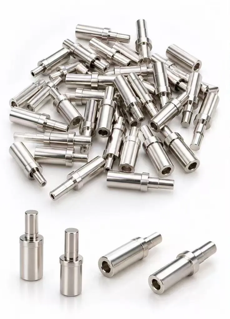
The part
A current-carrying pin that mates inside a charging gun. The barrel carries the current, the shoulder locates it in the housing, and the mating end decides how much heat the joint makes at full load.
Specification
These are the ranges we produce most often. If your drawing sits outside them, send it anyway — the answer will be honest, including when the answer is no.
| Material | Copper alloy (CuTe / H62 brass), or tell us the conductivity your design needs |
| Mating diameter | 2 – 8 mm typical |
| Overall length | 10 – 40 mm |
| Tolerance | ±0.02 mm on the mating diameter; tighter on request |
| Plating | Nickel under-layer + silver 3 – 8 µm, thickness verified by XRF |
| Edge | Deburred, R0.1 max — specified because it affects contact resistance, not appearance |
| Process | Cold heading → turning of the bore → deburr → barrel plating → screening |
Values shown are typical for this part family, not a catalogue limit. Final specification is agreed against your drawing.
Why it is difficult
A contact that looks correct can still fail in the field. These are the three we design the process around.
| 1. Plating too thin | Silver wears through at the mating point, copper oxidises, resistance climbs. Controlled by thickness measurement, not by plating time. |
| 2. Burr at the mating edge | A burr concentrates current and creates a local hot spot. Removed before plating, because plating over a burr keeps the burr. |
| 3. Eccentricity | If the bore is off-centre, the mating force is uneven and the contact area drops. Held by the fixture, checked on the projector. |
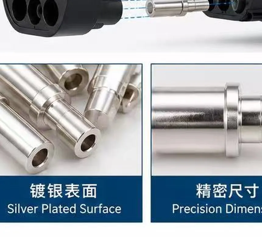
Edge and bore condition at the mating end — the surface that decides contact resistance.
Inspection
XRF spectrometer on the finished part, not on a test coupon.
Silver and nickel layers, per batch
Measured on assembled samples against the drawing limit.
At rated current, before shipping
Mating diameter, bore concentricity, overall length on the 2D projector.
First article + patrol inspection
Visual and tactile check under magnification before plating.
Every lot
Where it goes
High-current pins where heat generation at the contact is the limiting factor.
Lower current, but the same requirement on plating durability across mating cycles.
Internal high-current joints, often with a different housing interface.
Feasibility, process route and an indicative price in 48 hours — including when the answer is that turning is the better route.
Send a drawing